Set Appliance State:
| Isolate Mains Power to appliance as per TOPs P4 |
Set Multimeter to Resistance 
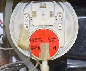
Remove leads from air pressure switch (make a note of their location)
Remove CN206 from the PCB
Remove CN206 from the PCB
Measurement:
Measure for resistance of the wiring harness from connector CN206 pins 1 (grey) & 2 (grey) to the disconnected leads at the air pressure switch.
Expect continuity / zero resistance on each wire.
Also visually inspect the condition of the wiring and connectors.
Note.
Ensure a good connection is made during resistance tests.
Expect continuity / zero resistance on each wire.
Also visually inspect the condition of the wiring and connectors.
Note.
Ensure a good connection is made during resistance tests.


Isolate as per TOPs P4
and refit as necessary