Set Appliance State:
| Isolate Mains Power to appliance as per TOPs P4 |
Set Multimeter to Resistance 
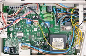
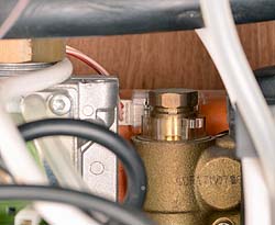
Remove connectors CN203 from the PCB and from the DHW flow sensor
Measurement:
Measure the resistance of the wiring harness from connector CN203, pins 1 (red lead), 2 (white lead) and 3 (pink lead) to the corresponding lead of the removed flow switch connector.
Expect continuity / zero resistance on each wire.
Expect continuity / zero resistance on each wire.


Isolate as per TOPs P4
and refit as necessary