Set Appliance State:
| Isolate Mains Power to appliance as per TOPs P4 |
Set Multimeter to Resistance 
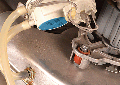
Remove connector CN8 from the PCB
Remove the leads from the APS making a note of their positions
Remove the leads from the APS making a note of their positions
Measurement:
Test 1:
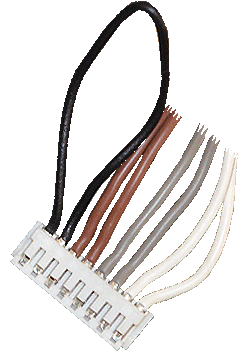
Measure the resistance between pin 5 (grey) on connector CN8
and the grey lead from connector 3 on the APS.
Test 2:
Measure the resistance between pin 6 (grey) on connector
CN8 and the grey lead from connector 1 on the APS.
Note:
For ease use a crocodile clip on the disconnected APS lead.
Expect continuity/zero resistance on both tests.
Also visually check the condition of the harness.


Isolate as per TOPs P4
and refit as necessary