Set Appliance State:
| Isolate Mains Power to appliance as per TOPs P4 |
Set Multimeter to Resistance 
CH Demand
Hinge down PCB
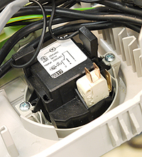
Disconnect the two leads from the timers micro switch assy.
Disconnect the two leads from the timers micro switch assy.
Measurement:
Measure the resistance across clock micro switch terminals as illustrated.
(Two connections to the rear of clock assembly)
Expected resistance short circuit.
(Two connections to the rear of clock assembly)
Expected resistance short circuit.

Isolate as per TOPs P4
and refit as necessary