Set Appliance State:
Mode selector switch to Off/Reset position
Set Multimeter to AC Volts 
Turn Hot Water Tap On
Isolate Mains Power to appliance as per TOPs P4
Hot water temperature control set to maximum
Note:
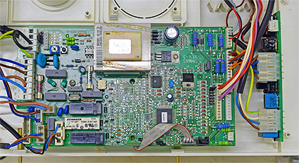
To perform this test safely remove the ignition PCB from its cradle and refit
in the upturned position with the terminals exposed and facing the main PCB
Use insulation mat as necessary
Hot water temperature control set to maximum
Note:
To perform this test safely remove the ignition PCB from its cradle and refit
in the upturned position with the terminals exposed and facing the main PCB
Use insulation mat as necessary
| WARNING! - Mains voltage is expected during test follow TOPs P4 live testing procedure |
Measurement:
Mode selector switch to DHW position. Allow fan to run and ignition sequence to commence.
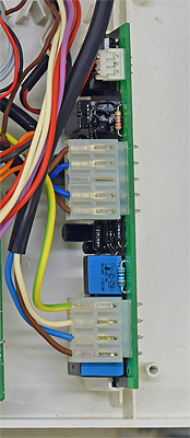
Measure for AC Voltage between a suitable earth and connections
blue and brown at connector 2 on Ignition PCB.
Test 1:
Connector 2, blue connection. Shortly after the fan begins to run voltage should
increase from 0V to mains voltage for approximately 3 seconds then drop to
below 200V AC for 5 seconds (as appliance attempts to spark).
Test 2:
Reset appliance then repeat test on brown connection.
Results should be the same as in test 1.
Note: Connectors are numbered left to right with 2 being furthest from the two pin connector on the left.


Isolate as per TOPs P4
and refit as necessary