Set Appliance State:
| Isolate Mains Power to appliance as per TOPs P4 |
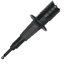
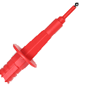
Set Multimeter to Resistance 
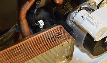
Remove the air intake
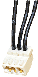
Remove the connector from the DHW flow sensor
Remove the connector from the DHW flow sensor
Measurement:
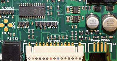
Measure the resistance between pins 3, 4 and 6 on
connector X5 on the PCB to the disconnected DHW flow sensor connector, as per the table below;
Expect continuity / zero resistance on each of the wires.
Also visually inspect the harness for good general condition.
Note.
Place the probe in the small holes on the PCB.
connector X5 on the PCB to the disconnected DHW flow sensor connector, as per the table below;
| Pin on connector X5 | DHW flow sensor connector | 3 | 1 |
| 4 | 3 |
| 6 | 2 |
Expect continuity / zero resistance on each of the wires.
Also visually inspect the harness for good general condition.
Note.
Place the probe in the small holes on the PCB.


Isolate as per TOPs P4
and refit as necessary