Set Appliance State:
| Isolate Mains Power to appliance as per TOPs P4 |
Set Multimeter to Resistance 
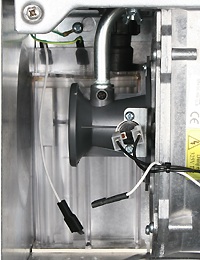
Disconnect the rectification lead from the condensate trap at the inline connector
Remove the 6 pin connector from the PCB
Disconnect the rectification lead from the sensing electrode (make sure it does not touch the boiler case or components - wrap in insulation tape if necessary)
Remove the 6 pin connector from the PCB
Disconnect the rectification lead from the sensing electrode (make sure it does not touch the boiler case or components - wrap in insulation tape if necessary)
Measurement:
Test 1:
Measure the resistance between the inline connector removed from the condensate trap and pin 1 (white wire) on the 6 pin connector.
Expect continuity / zero resistance.
Test 2:
Measure resistance between the spade connector removed from the condensate trap and a suitable earth.
Expected open circuit / O.L.
Are the resistances measured as expected?


Isolate as per TOPs P4
and refit as necessary