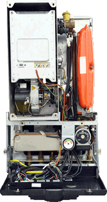
Set Appliance State:
| Isolate Mains Power to appliance as per TOPs P4 |
Set Multimeter to Resistance 
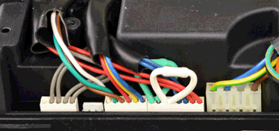
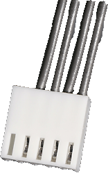
Remove the 5 pin connector from the PCB
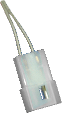
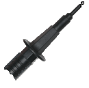
Disconnect the flow switch at the inline connector
Disconnect the flow switch at the inline connector
Measurement:
Measure the resistance across each of the grey wires running to the primary circuit flow switch on the 5 pin connector (right hand pair).
Expect continuity / zero resistance.
Also visually inspect the condition of the harness and connectors.
Are the harness checks satisfactory?
Expect continuity / zero resistance.
Also visually inspect the condition of the harness and connectors.
Are the harness checks satisfactory?


Isolate as per TOPs P4
and refit as necessary