Set Appliance State:
| Isolate Mains Power to appliance as per TOPs P4 |
Set Multimeter to Resistance 
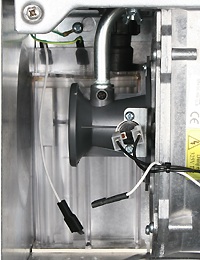
Disconnect the rectification lead from the condensate trap at the inline connector
Remove the 6 pin connector from the PCB
Remove the 6 pin connector from the PCB
Measurement:
Measure the resistance between the inline connector removed from the condensate trap and pin 1 (white wire) on the 6 pin connector.
Expect continuity / zero resistance.
Also visually inspect the rectification harness throughout its entire length including the sections to the condensate trap and rectification electrode checking there is no damaged insulation and that the connectors are a tight fit.
Are the harness checks satisfactory?


Isolate as per TOPs P4
and refit as necessary