Set Appliance State:
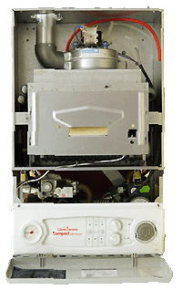
| Isolate Mains Power to appliance as per TOPs P4 |
Set Multimeter to Resistance 
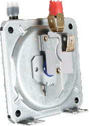
Remove the wires from the air pressure switch noting their locations
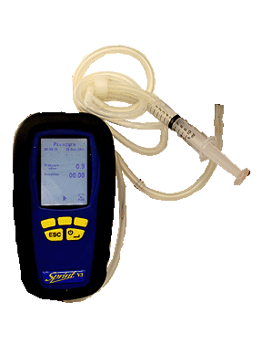
Connect the air pressure switch charge kit to +ve connection on the air pressure switch
Connect the air pressure switch charge kit to +ve connection on the air pressure switch
Measurement:
Increase the pressure via the syringe to that indicated on the pressure switch.
Measure the resistance between the common and normally open terminals on the air pressure switch.
Expect continuity or zero resistance.
Note:
1. If continuity is not obtained when the specified pressure
is applied it is permissible to increase the pressure by 50%
100 Pascals = 1mbar / 50 Pascals = 0.5mbar.
2. The air pressure switch may differ in appearance but the test points (common and normally open) remain the same.

Isolate as per TOPs P4
and refit as necessary