Set Appliance State:
| Isolate Mains Power to appliance as per TOPs P4 |
Set Multimeter to DC Volts 
Turn Hot Water Tap On
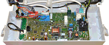
Gain access to PCB (use Insulation Mat as required)
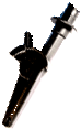
Remove electrical connector from fan assembly and make safe
Remove electrical connector from fan assembly and make safe
| WARNING! - Mains voltage is expected during test follow TOPs P4 live testing procedure |
Measurement:
Reset appliance if required (Press reset button once then release)
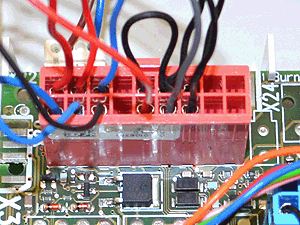
When the boiler has recognised a DHW demand (tap symbol on display) measure for DC volts between pin 4 (grey) on connector X20 and the earth point on the boiler chassis.
Expected voltage approximately 22.0 Vdc.
Note:
Each pin on the PCB connector is numbered.
Click here for information on hall sensors


Isolate as per TOPs P4
and refit as necessary