Set Appliance State:
| Isolate Mains Power to appliance as per TOPs P4 |
Set Multimeter to DC Volts 
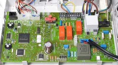
Gain access to PCB (use Insulation Mat as required)
| WARNING! - Mains voltage is expected during test follow TOPs P4 live testing procedure |
Measurement:
Test 1:
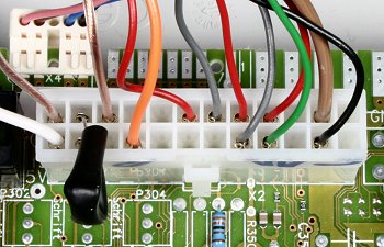
Measure the voltage between pin 7 (grey wire) and pin 20 (grey wire) at the large multi-pin connector (X2) on the PCB, as shown in the photograph.
Voltage should be approximately 24V DC.
Test 2:
Apply a CH demand.
Continue measuring the voltage between pin 7 and 20.
Shortly after the fan begins to run the voltage should drop from 24V DC to 0V DC.