Set Appliance State:
| Isolate Mains Power to appliance as per TOPs P4 |
Set Multimeter to Resistance 
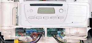
Remove electrical connectors X2 from the PCB and
to the DHW flow sensor
to the DHW flow sensor
Measurement:
Measure for resistance across each wire of the DHW flow sensor harness, 2,3,6 of X2 connector to the corresponding wire on the sensor connector.
(e.g. yellow lead X2 connector to yellow lead of flow sensor connector)
Expect continuity / zero resistance on each wire.
Also visually inspect the harness for good general condition.
Are the resistances as expected and is the harness in good condition?
Note.
Ensure a good connection is made as misdiagnosis may occur.


Isolate as per TOPs P4
and refit as necessary