Set Appliance State:
| Isolate Mains Power to appliance as per TOPs P4 |
Set Multimeter to Resistance 
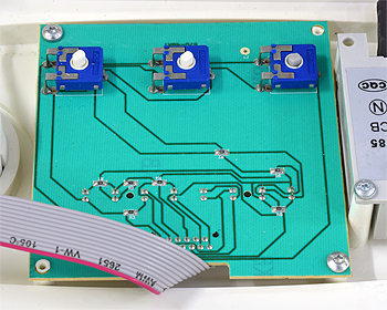
Disconnect X1 (ribbon cable) from main PCB
(this affects resistances and must be done to prevent misdiagnosis)
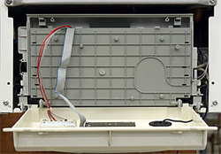
Gain access to back of display PCB
(this affects resistances and must be done to prevent misdiagnosis)
Gain access to back of display PCB
Measurement:
Test 1:
Set DHW temperature control to maximum.
Measure the resistance between connections 1 and 3 on the display PCB.
Resistance should be less than 10Ω.
Measure the resistance between connections 2 and 3 on the display PCB.
Resistance should be approximately 2.8kΩ.
Test 2:
Set DHW temperature control to minimum.
Measure the resistance between connections 1 and 3 on the display PCB.
Resistance should be approximately 2.8kΩ.
Measure the resistance between connections 2 and 3 on the display PCB.
Resistance should be less than 10Ω.


Isolate as per TOPs P4
and refit as necessary