Set Appliance State:
| Isolate Mains Power to appliance as per TOPs P4 |
Set Multimeter to Resistance 
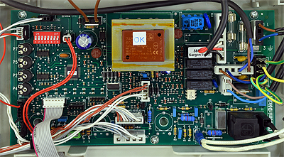
Remove connector X17 from the PCB
Measurement:
Test 1. Measure for resistance across the blue and brown leads of connector X17.
Expected resistance between 740 and 800Ω (0.74k to 0.8kΩ) (see note).
Test 2: Measure for resistance across the brown lead of connector X17 and a suitable earth connection.
Expected resistance greater than 1MΩ (or O.L.)
Note:
Gas valve solenoids are fitted in parallel. A resistance that is
not very close to 0.77kΩ will indicate a faulty solenoid.


Isolate as per TOPs P4
and refit as necessary