Set Appliance State:
| Isolate Mains Power to appliance as per TOPs P4 |
Set Multimeter to DC Volts 
CH Demand
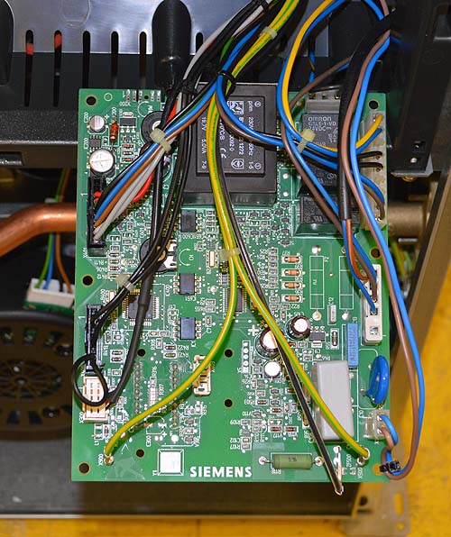
Gain access to PCB (use Insulation Mat as required)
Place PCB in test position, click HERE for guidance
Remove connector from spark generator and make safe
Place PCB in test position, click HERE for guidance
Remove connector from spark generator and make safe
| WARNING! - Mains voltage is expected during test follow TOPs P4 live testing procedure |
Measurement:
Reset appliance if required.
Allow ignition sequence to commence.
Measure for DC voltage across pins 2 & 5 of PCB connector X2 (see note.)
Expected voltage will vary but it should be at least 100V DC.
Make a note of the voltage recorded as it will be needed on the next test.
Note.
Voltage duration is approximately 5 seconds during the sparking phase of ignition with a 15 second interval, the boiler will enter lockout after 3 attempts of ignition, reset boiler as required until test is complete.

Isolate as per TOPs P4
and refit as necessary