Set Appliance State:
| Isolate Mains Power to appliance as per TOPs P4 |
Set Multimeter to Resistance 
Disconnect inline connector to flow switch
Measurement:
Measure the resistance (continuity) across the flow switch harness leads.
Connections are;
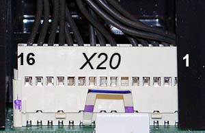
X20 connector pins 11 & 12 to inline connector which connects to the PCB.
Expected resistance is continuity (zero resistance).
Note.
Ensure a good connection is made or misdiagnosis will occur.
Connections are;
X20 connector pins 11 & 12 to inline connector which connects to the PCB.
Expected resistance is continuity (zero resistance).
Note.
Ensure a good connection is made or misdiagnosis will occur.


Isolate as per TOPs P4
and refit as necessary