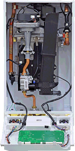
Set Appliance State:
| Isolate Mains Power to appliance as per TOPs P4 |
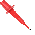
Set Multimeter to Resistance 
Gain access to PCB
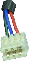
Remove connector to flow sensor
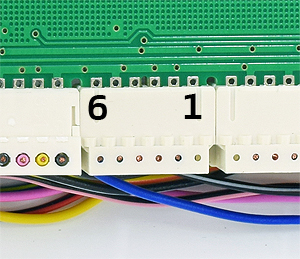
Pull X6 back slightly to expose test pins
Remove connector to flow sensor
Pull X6 back slightly to expose test pins
Measurement:
Check for continuity (zero resistance) of each of the
3 wires running between X6 and the disconnected plug.
Red = X6 Pin 4.
Black = X6 Pin 5
Blue = X6 Pin 6.
Inspect harness and connectors for good overall condition.
Note:
Wires may be multicoloured.
3 wires running between X6 and the disconnected plug.
Red = X6 Pin 4.
Black = X6 Pin 5
Blue = X6 Pin 6.
Inspect harness and connectors for good overall condition.
Note:
Wires may be multicoloured.


Isolate as per TOPs P4
and refit as necessary