Set Appliance State:
| Isolate Mains Power to appliance as per TOPs P4 |
Set Multimeter to Resistance 
Hinge down the PCB housing
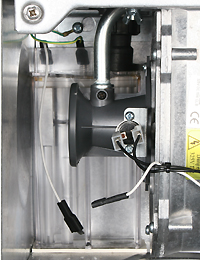
Disconnect the rectification lead
from the condensate trap
Disconnect the 6 way connector from the PCB
Disconnect the rectification lead from the sensing electrode. Make sure it does not touch the boiler case or components (Wrap in insulation tape if necessary)
Disconnect the rectification lead
from the condensate trap
Disconnect the 6 way connector from the PCB
Disconnect the rectification lead from the sensing electrode. Make sure it does not touch the boiler case or components (Wrap in insulation tape if necessary)
Measurement:
Test 1:
Test for continuity between the spade connector disconnected from the condensate trap and connection 1 (white wire) on the Molex connector.
Expected result continuity (zero resistance).
Test 2:
Measure resistance between the spade connector disconnected from the condensate trap and a suitable earth point.
Expected result Open Circuit.


Isolate as per TOPs P4
and refit as necessary