Set Appliance State:
| Isolate Mains Power to appliance as per TOPs P4 |
Set Multimeter to Resistance 
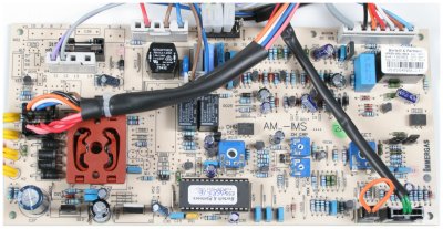
There are two thermistor sensors on the appliance they are located at the R/H side of the heat exchanger in the flow and return header due to the position it will be easier to check the resistance of the thermistor at the plug connections on the PCB
Note: The resistance will depend on the temperature of the appliance
the higher the temperature the lower the resistance
Note: The resistance will depend on the temperature of the appliance
the higher the temperature the lower the resistance
Measurement:
Test 1: Remove connector X11 from the PCB.
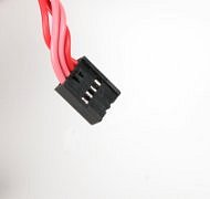
Check resistance across the red leads at the disconnected connector.
The resistance should conform to the table below:
Test 2: Remove connector X8 from the PCB.
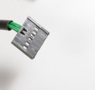
Check resistance across green leads at the disconnected connector.
The resistance should conform to the table below:
Check resistance across the red leads at the disconnected connector.
The resistance should conform to the table below:
Test 2: Remove connector X8 from the PCB.
Check resistance across green leads at the disconnected connector.
The resistance should conform to the table below:
| Temperature °C | Resistance in kOhms | 20 - 30 | 8 to 16 |
| 30 - 40 | 6 to 10 |
| 40 - 50 | 3.9 to 8 |
| 50 - 60 | 2.5 to 5.5 |
| 60 - 70 | 1.5 to 3.0 |