Set Appliance State:
| Isolate Mains Power to appliance as per TOPs P4 |
Set Multimeter to Resistance 
For access behind the control panel
Release the fixing screw located at the top of the case
front panel and lift the panel upwards from its locating
pins and then forwards from the boiler.
Remove the two fixing screws that secure the control panel and lower the panel.
For access to the control panel components.
Remove the five screws securing the rear cover and careful raise the cover from the control panel. When replacing the cover ensure no wires are trapped and all the wiring is secured secure with screws previously removed do not over tighten.
Observation:
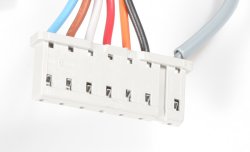
Disconnect connector marked X7 from the PCB.
Measure resistance across connections corresponding to pins 24
and 25 (red lead and white lead) at the disconnected connector.
Expected resistance closed circuit, zero ohms plus test lead resistance.
Measure resistance across connections corresponding to pins 24
and 25 (red lead and white lead) at the disconnected connector.
Expected resistance closed circuit, zero ohms plus test lead resistance.


Isolate as per TOPs P4
and refit as necessary