Set Appliance State:
| Isolate Mains Power to appliance as per TOPs P4 |
Set Multimeter to AC Volts 
For access behind the control panel
Release the fixing screw located at the top of the case front panel and lift the panel upwards from its locating pins and then forwards from the boiler.
Remove the two fixing screws that secure the control panel and lower the panel.
For access to the control panel components.
Remove the five screws securing the rear cover and careful raise the cover from the control panel. When replacing the cover ensure no wires are trapped and all the wiring is secured secure with screws previously removed do not over tighten.
| WARNING! - Mains voltage is expected during test follow TOPs P4 live testing procedure |
Observation:
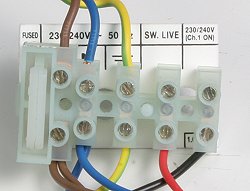
Test 1: Measure voltage across the terminals marked L (brown wire)
and the earth terminal (green/yellow wire) on the main terminal strip.
Expected voltage mains voltage (230 volts AC)
Test 2: Measure voltage across the terminals marked N (blue wire)
and the earth terminal (green/yellow wire) on the main terminal strip.
Expected voltage zero to 15 volts AC.
and the earth terminal (green/yellow wire) on the main terminal strip.
Expected voltage mains voltage (230 volts AC)
Test 2: Measure voltage across the terminals marked N (blue wire)
and the earth terminal (green/yellow wire) on the main terminal strip.
Expected voltage zero to 15 volts AC.


Isolate as per TOPs P4
and refit as necessary