Set Appliance State:
| Isolate Mains Power to appliance as per TOPs P4 |
Set Multimeter to Resistance 
Remove the tubes from the air pressure switch (noting their locations)
Connect the APS testing kit and FGA to the APS (P1 / +ve connection)
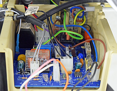
Disconnect plug for the air pressure switch at the PCB (refer to picture)
Connect the APS testing kit and FGA to the APS (P1 / +ve connection)
Disconnect plug for the air pressure switch at the PCB (refer to picture)
Measurement:
Steadily increase the pressure using
the syringe to that shown on the APS.
(switching pressure may be shown on rear of
APS, remove / loosen securing screw to view)
Measure the resistance between the red
and yellow wires at the disconnected plug.
Continuity / zero resistance should be measured.
Notes:
1. If continuity is not obtained it is
permissible to increase the pressure by 50%.
2. 100 Pascals = 1mb / 50 Pascals = 0.5mb.


Isolate as per TOPs P4
and refit as necessary