Set Appliance State:
| Isolate Mains Power to appliance as per TOPs P4 |
Set Multimeter to DC Volts 
CH Demand
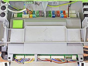
Gain access to PCB (use Insulation Mat as required)
| WARNING! - Mains voltage is expected during test follow TOPs P4 live testing procedure |
Measurement:
Reset appliance as necessary (hold down both arrow buttons until display changes).
Allow boiler self-check to complete and ignition sequence to begin.
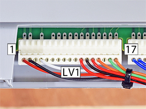
Measure the DC voltage between in pin 4 (white) at LV1 on the PCB to a suitable earth point.
Before the flame ignites expect 0V DC (multimeter display may flicker during sparking stage)
When the flame is lit expect 5V DC or greater.
Is the rectification voltage as expected?
Note:
Connector may differ slightly in appearance but this does not affect the test.
Allow boiler self-check to complete and ignition sequence to begin.
Measure the DC voltage between in pin 4 (white) at LV1 on the PCB to a suitable earth point.
Before the flame ignites expect 0V DC (multimeter display may flicker during sparking stage)
When the flame is lit expect 5V DC or greater.
Is the rectification voltage as expected?
Note:
Connector may differ slightly in appearance but this does not affect the test.


Isolate as per TOPs P4
and refit as necessary