Set Appliance State:
| Isolate Mains Power to appliance as per TOPs P4 |
Set Multimeter to Resistance 
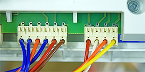
Disconnect connector X10 from the PCB
Measurement:
Test 1:
Measure the resistance between the fan neutral (marked 13.5) on X11 and fan wires (marked 13.1, 13.2 and 13.3) on connector X10 in turn.
Expect greater than 1M Ohm on each test.
Test 2:
Measure the resistance between each fan wire (marked 13.1, 13.2 and 13.3) on X10 and a suitable earth point.
Expect greater than 1M Ohm on each test.
Disconnect connector X11 from the PCB.
Test 3:
Measure the resistance between the fan neutral
(marked 13.5) on X11 and fan live (marked 13.4) on X11.
Expect greater than 1M Ohm.
Test 4:
Measure the resistance between the fan neutral
(marked 13.5) on X11 and a suitable earth point.
Expect greater than 1M Ohm.


Isolate as per TOPs P4
and refit as necessary