Set Appliance State:
| Isolate Mains Power to appliance as per TOPs P4 |
Set Multimeter to Resistance 
Disconnect electrical connector from fan assembly
Measurement:
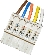
Measure for continuity (zero resistance)
on each wire of the fan harness.
Yellow to Yellow (13.1 on X10).
Orange to Orange (13.2 on X10).
White to White (13.3 on X10).
Brown to Brown (13.4 on X11).
Blue to Blue (13.5 on X11).
Note:
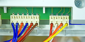
1. Identification numbers for the fan
connections are located on the PCB.
2. For ease of testing use the holes above
the connectors on the PCB.
on each wire of the fan harness.
Yellow to Yellow (13.1 on X10).
Orange to Orange (13.2 on X10).
White to White (13.3 on X10).
Brown to Brown (13.4 on X11).
Blue to Blue (13.5 on X11).
Note:
1. Identification numbers for the fan
connections are located on the PCB.
2. For ease of testing use the holes above
the connectors on the PCB.


Isolate as per TOPs P4
and refit as necessary