Set Appliance State:
| Isolate Mains Power to appliance as per TOPs P4 |
Set Multimeter to AC Volts 
CH Demand
Gain access to PCB (use Insulation Mat as required)
Temperature control set to MAX
Temperature control set to MAX
| WARNING! - Mains voltage is expected during test follow TOPs P4 live testing procedure |
Measurement:
Reset boiler as necessary, allow the appliance to complete its self check.
Voltage will only be present during the sparking stage of the ignition sequence.
Test 1:
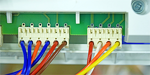
Measure the voltage between the Red pin marked 7.1 and the Blue pin marked 7.2 on X11 connector at the PCB.
Test 2:
Measure the voltage between the Orange pin marked 7.3 and the Blue pin marked 7.2 on X11 connector at the PCB.
Mains voltage expected on both tests.
Voltage will only be present during the sparking stage of the ignition sequence.
Test 1:
Measure the voltage between the Red pin marked 7.1 and the Blue pin marked 7.2 on X11 connector at the PCB.
Test 2:
Measure the voltage between the Orange pin marked 7.3 and the Blue pin marked 7.2 on X11 connector at the PCB.
Mains voltage expected on both tests.

Isolate as per TOPs P4
and refit as necessary