Set Appliance State:
| Isolate Mains Power to appliance as per TOPs P4 |
Set Multimeter to AC Volts 
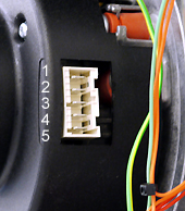
Remove the connector from the fan and make safe
Ensure NO Demands
Ensure NO Demands
| WARNING! - Mains voltage is expected during test follow TOPs P4 live testing procedure |
Measurement:
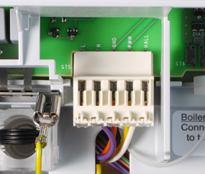
Measure the voltage between each of the wires at the PCB fan connector as listed below:
Orange to Brown.
Yellow to Brown.
White to Brown.
With the connector removed from the fan is mains voltage present on any of the wires?
Notes:
1. Ensure a good connection is made, this can be achieved by inserting the probe in the slot above the wire on the fan connector (A) or into the small test point on the PCB (B) (the connector must remain attached to the PCB).
2.Brown is the fan's neutral, this must be used and not any other neutral point.


Isolate as per TOPs P4
and refit as necessary