Set Appliance State:
| Isolate Mains Power to appliance as per TOPs P4 |
Set Multimeter to Resistance 
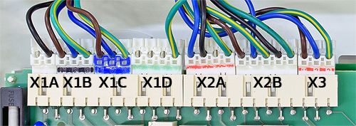
Remove connector X2B from the PCB
Measurement:
Test 1.
Measure the resistance between pin 1 (brown) and
pin 2 (blue) at X2B on the PCB.
Expected resistance greater than 1MΩ (or O.L).
Test 2.
Measure for resistance between pin 1 (brown)
on X2B to a suitable earth connection.
Expected resistance greater than 1MΩ (or O.L).
Note:
Wires may be multi coloured.


Isolate as per TOPs P4
and refit as necessary