Set Appliance State:
| Isolate Mains Power to appliance as per TOPs P4 |
Set Multimeter to Resistance 
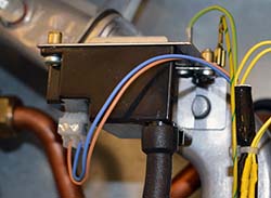
Disconnect flame sense lead from electrode
Disconnect flame sense lead from the PCB
Disconnect flame sense lead from the PCB
Measurement:
Test 1:
Carry out a continuity check of the earth lead between the PCB
connector and the earth tab.
Expect zero resistance.
Test 2:
Carry out a continuity check of the flame sense lead between the PCB connector and detection electrode connection
Expect zero resistance.
Test 3:
Thoroughly inspect the condition of the earth and rectification leads, looking for damaged insulation, evidence of the lead being trapped or heat damaged and excessively tight bends or kinks, confirm that the spark generator earthing screw is present and tight.


Isolate as per TOPs P4
and refit as necessary