Set Appliance State:
| Isolate Mains Power to appliance as per TOPs P4 |
Set Multimeter to Resistance 
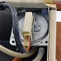
Remove the tubes from the air pressure switch (noting their locations)
Connect the APS testing kit and FGA to the APS (positive connection)
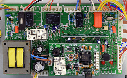
Disconnect plug marked CON11 at the PCB
Connect the APS testing kit and FGA to the APS (positive connection)
Disconnect plug marked CON11 at the PCB
Measurement:
Steadily increase the pressure using
the syringe to that shown on the APS.
(switching pressure may be shown on rear of
APS, remove / loosen securing screw to view)
Measure the resistance between the red
and yellow wires at the disconnected plug.
Continuity / zero resistance should be measured.
Notes:
1. If continuity is not obtained it is
permissible to increase the pressure by 50%.
2. 100 Pascals = 1mb / 50 Pascals = 0.5mb.


Isolate as per TOPs P4
and refit as necessary