Isolate Mains Power to appliance as per TOPs P4
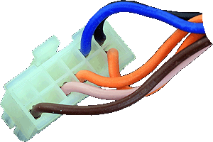
Remove the connector from the pump assembly
Remove the pump connector from the PCB
Remove the connector from the pump assembly
Remove the pump connector from the PCB
Observation:
Test 1:
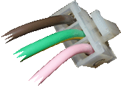
Measure the resistance of the brown and pink wires from the pcb connector to the pump connector.
Expect continuity / zero resistance on each wire.
Test 2:
Measure the resistance from the green wire at the pump connector to a suitable earth.
Expect continuity / zero resistance.
Test 3:
Visually inspect the condition of the brown, pink and green wires in the harness checking the condition of the insulation and that there is no evidence of shorts present.


Isolate as per TOPs P4
and refit as necessary