Set Appliance State:
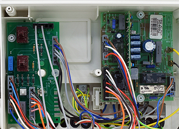
| Isolate Mains Power to appliance as per TOPs P4 |
Set Multimeter to Resistance 
Disconnect PCB to PCB harness from CN104 on the control PCB and CN100 on the ignition PCB
Measurement:
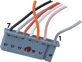
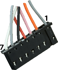
Check for continuity (zero resistance) between each of the 7 wires running between the two PCBs.
Inspect harness and connectors for good overall condition.
Note:
Wires are not all on the same pin number across both
harnesses, refer to table below.
Inspect harness and connectors for good overall condition.
Note:
Wires are not all on the same pin number across both
harnesses, refer to table below.


Isolate as per TOPs P4
and refit as necessary