Set Appliance State:
| Isolate Mains Power to appliance as per TOPs P4 |
Set Multimeter to Resistance 
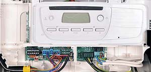
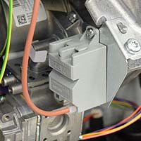
Remove electrical connector to spark generator and connector X21 from the PCB
Measurement:
Measure for resistance across each wire of the spark generator harness as listed below:
Pin 4 (blue lead) X21 and pin 2 spark generator connector.
Pin 1 (brown lead) X21 and pin 1 spark generator connector.
Pin 2 (black lead ) X21 and pin 3 spark generator connector.
Expect continuity / zero resistance on each wire.
Also visually inspect the harness for good general condition.
Are the resistances as expected and is the harness in good condition?
Note.
Ensure a good connection is made as misdiagnosis may occur.
Expect continuity / zero resistance on each wire.
Also visually inspect the harness for good general condition.
Are the resistances as expected and is the harness in good condition?
Note.
Ensure a good connection is made as misdiagnosis may occur.

Isolate as per TOPs P4
and refit as necessary