Set Appliance State:
| Isolate Mains Power to appliance as per TOPs P4 |
Set Multimeter to DC Volts 
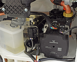
Disconnect pump speed control and make safe
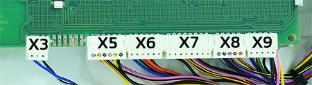
Pull X5 back slightly to expose test points
Gain access to PCB (use insulation mat as necessary)
Ensure no demands
Pull X5 back slightly to expose test points
Gain access to PCB (use insulation mat as necessary)
Ensure no demands
| WARNING! - Mains voltage is expected during test follow TOPs P4 live testing procedure |
Measurement:
Test 1:
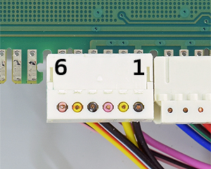
Measure the DC voltage between pin 3 (pink)
and pin 1 (black) at X5 on the PCB.
Voltage should be approximately 5V DC.
Test 2:
Measure the DC voltage between pin 2 (yellow)
and pin 1 (black) at X5 on the PCB.
Voltage should be approximately 0.7V DC.
Test 3:
Allow fan purge to complete (4 mins after power on).
Again measure the DC voltage between pin 2 (yellow) and pin 1 (black) at X5 on the PCB.
Voltage should now be approximately 5V DC.


Isolate as per TOPs P4
and refit as necessary